It is really important that you know how to draw in 3rd Angle orthographic projection for the GCSE Engineering exam. In the exam you will be asked to complete a 3rd Angle orthographic projection of a product. Below the information about 3rd Angle orthographic projection there are some exam questions to download and test yourself. Tip Tip: Make sure you know how to show hidden detail and cross sections
Orthographic drawings contain all the information needed to make an object. The information must be accurate, so others can understand and interpret them.
Orthographic drawings are best used when:
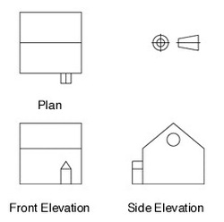
Orthographic drawings show three views of the object:
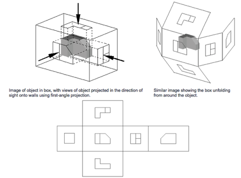
Third angle projection
This is the standard layout which you will be expected to use in the exam and in design projects and activities. The view or elevation you see from the left of the original object is drawn on the left. The view you see from the right is drawn on the right. What you see from above is drawn above. See picture below.
Orthographic drawings are best used when:
- you are producing construction drawings
- accurate technical information about sizes is needed
- many separate parts are needed
Orthographic drawings show three views of the object:
- the plan (from above)
- front elevation (front view)
- side elevation (side view).
Third angle projection
This is the standard layout which you will be expected to use in the exam and in design projects and activities. The view or elevation you see from the left of the original object is drawn on the left. The view you see from the right is drawn on the right. What you see from above is drawn above. See picture below.
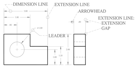
Dimensions
Dimensions are always in millimetres and written above the dimension line. Vertical dimensions are put on the left-hand side of the vertical dimension line, so when you turn the drawing round 90° it can be read from left to right. The projection lines should stop short of the object by 2mm. The smallest dimensions are put nearest the object. These drawings are vital for giving precise information, but they don't give an immediate idea of how the final object will look. See picture below.
Dimensions are always in millimetres and written above the dimension line. Vertical dimensions are put on the left-hand side of the vertical dimension line, so when you turn the drawing round 90° it can be read from left to right. The projection lines should stop short of the object by 2mm. The smallest dimensions are put nearest the object. These drawings are vital for giving precise information, but they don't give an immediate idea of how the final object will look. See picture below.
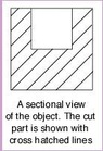
Sections
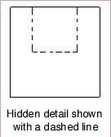
A section is generally a specialist version of an orthographic drawing where you need to show details of the design which are hidden; for example internal features, or the material thickness of the product. One example of this would be the depth of a hole in a wooden block. You could show this by either of the following methods:
A section is generally a specialist version of an orthographic drawing where you need to show details of the design which are hidden; for example internal features, or the material thickness of the product. One example of this would be the depth of a hole in a wooden block. You could show this by either of the following methods:
|
|
When using sectional views, ensure that:
- the path of the section (or cut) is clearly shown on another view (often a plan)
- the cut sections are crosshatched with 45° lines
- when two cut sections are next to each other hatching is done at different angles
- exposed components such as bolts are shown uncut
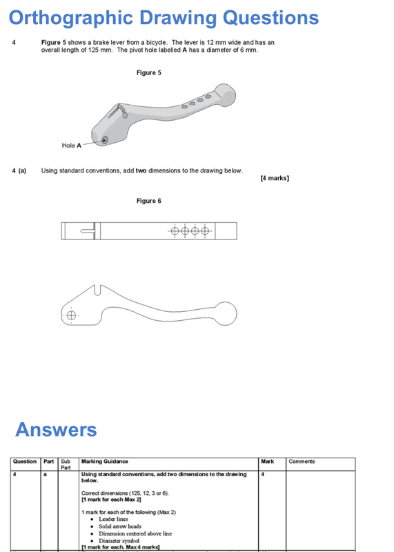
3rd Angle Projection Exam Questions:
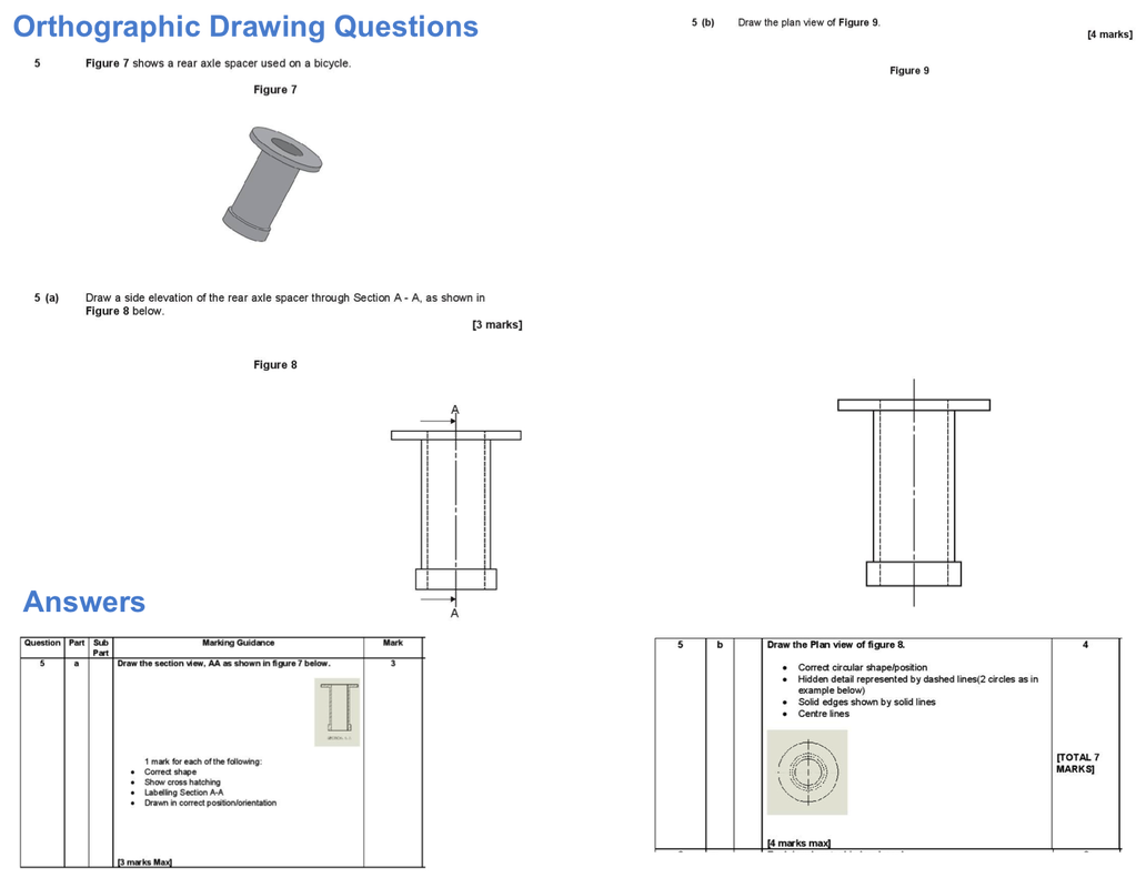
| 3rd_angle_exam_question_to_download.pptx |
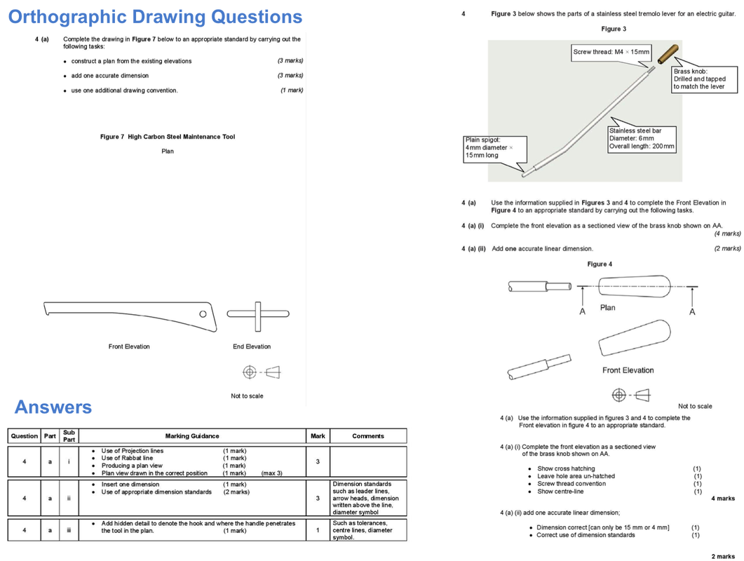
| 3rd_angle_exam_question_to_download2.pdf |
| drawing_techniques.docx |
